Visualization Interface Usage
TIAToolbox provides a flexible visualization tool for viewing slides and overlaying associated model outputs or annotations. It is a browser-based UI built using TIAToolbox and Bokeh. The following assumes TIAToolbox has been installed per the instructions here: Installation.
1. Launching the Interface
Start the interface using the command:
tiatoolbox visualize --slides path/to/slides --overlays path/to/overlays
This should cause the interface to appear in a new browser tab. Alternatively, you can provide just one base path; in this case, it is assumed that slides and overlays are in subdirectories of that provided directory called ‘slides’ and ‘overlays’ respectively:
tiatoolbox visualize --base-path path/to/parent_of_slides_and_overlays
In the folder(s) that your command pointed to, there should be the items you want to visualize, following the conventions in Data formats.
If you need to change the port on which the interface is launched from the default of 5006, you can do so using the –port flag:
tiatoolbox visualize --slides path/to/slides --overlays path/to/overlays --port 5001
Though in most cases this should not be necessary.
Launching on a Remote Machine
As the UI is browser-based, you can launch the interface on a remote machine by logging in via SSH and forwarding the relevant ports so that the visualization of the remote slides and overlays can be viewed in the browser on your local machine. For example, connect via SSH to your remote machine:
ssh -L 5006:localhost:5006 -L 5000:localhost:5000 user@remote_machine
This will start an SSH session where the two ports the interface uses by default (5006 and 5000) are forwarded.
You can then launch the interface on the remote machine as above (TIAToolbox must be installed on the remote machine) and open the browser on your local machine. Navigate to localhost:5006 to view the interface.
2. General UI Controls and Options
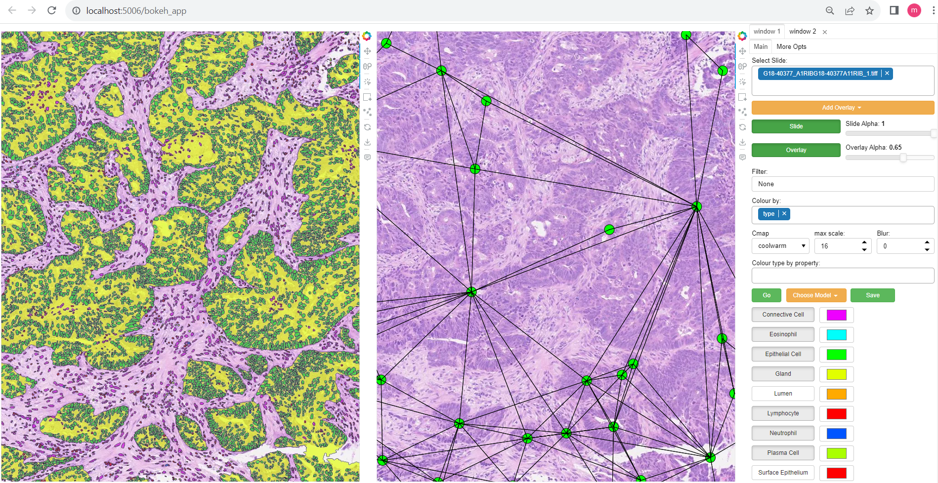
The interface is split into two main sections. The left-hand side contains the main window, which displays the slide and overlays (or potentially a linked pair of slide views), and the right-hand side contains a number of UI elements to control the display of the overlays.
The main window can be zoomed in and out using the mouse wheel and panned by clicking and dragging. The slide can be changed using the slide dropdown menu. The overlay can be changed, or additional overlays added using the overlay dropdown menu. Note: overlays involving a large number of annotations may take a short while to load. The alpha of the slide and overlay can be controlled using the slide and overlay alpha sliders respectively.
Information about the currently open slide can be found below the main window, including slide name, dimensions, and level resolution information.
Type and Layer Select
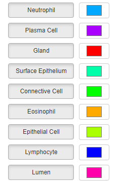
If annotations have a type property, this will be used to populate the type select boxes. This allows you to toggle on/off annotations of a specific type. You can also modify the default colors that each type is displayed in by using the color picker widgets next to each type name (note these will only have an effect if the property to color by is selected as ‘type’). Individual image overlays or graph overlays will also get their own toggle, labeled for example ‘layer_i’ or ‘nodes’, that can be used to toggle the respective overlays on or off.
Colormaps/Coloring by Property Values
Once you have selected a slide with the slide dropdown, you can add overlays by repeatedly choosing files containing overlays from the overlay drop menu. They will be overlaid on the slide as separate layers. In the case of segmentations, if your segmentations have the ‘type’ property as one of their properties, this can additionally be used to show/hide annotations of that specific type. Colors can be individually selected for each type if the randomly generated color scheme is not suitable.
You can select the property that will be used to color annotations in the color_by box. The corresponding property should be either categorical (strings or ints), in which case a dict-based color mapping should be used, or a float between 0-1 in which case a matplotlib colormap should be applied. There is also the option for the special case ‘color’ to be used. If your annotations have a property called color, this will be assumed to be an RGB value in the form of a tuple (R, G, B) of floats between 0-1 for each annotation which will be used directly without any mapping.
The ‘color type by property’ box allows annotations of the specified type to be colored by a different property to the ‘global’ one. For example, this could be used to have all detections colored according to their type, but for Glands, color by some feature describing them instead (their area, for example).
Running Models
Regions of the image can be selected, using either a box select or points, which can be sent to a model via selecting the model in the drop-down menu and then clicking go. Available so far is hovernet, and nuclick will likely be added in the future.
To save the annotations resulting from a model, or loaded from a .geojson or .dat (will be saved as a SQLiteStore .db file which will be far quicker to load), use the save button (for the moment it is just saved in a file ‘{slide_name}_saved_anns.db’ in the overlays folder).
Dual Window Mode
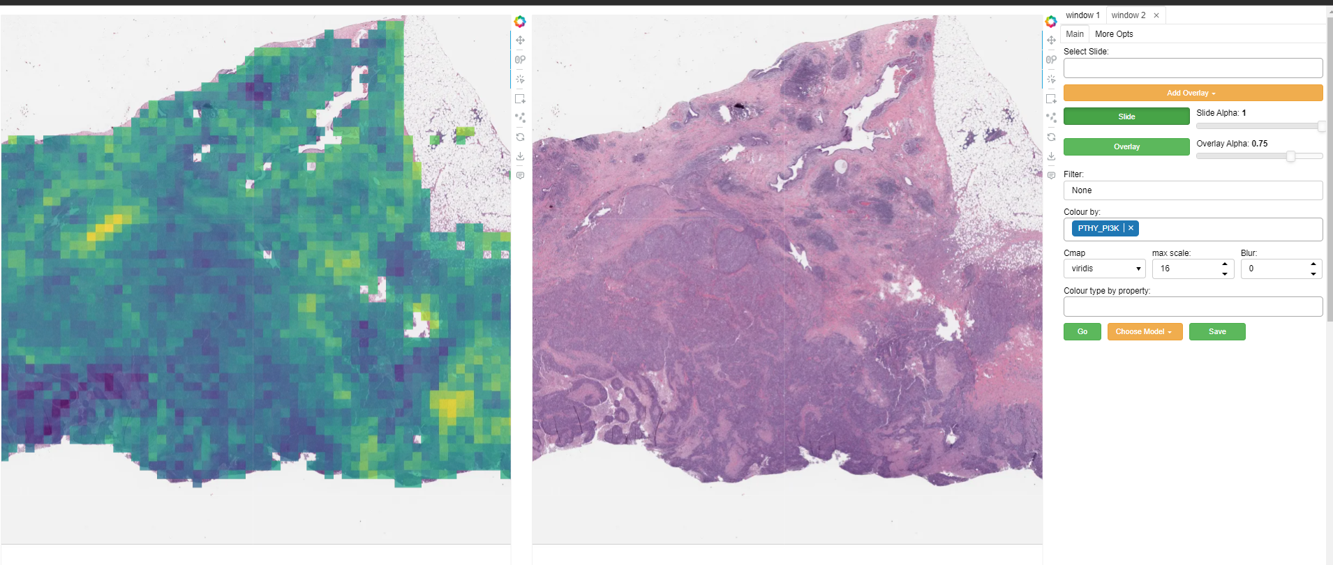
A second window can be opened by selecting the ‘window 2’ tab in the top right. This will open the currently selected slide in a second window as illustrated above. The overlay shown in each window can be controlled independently to allow comparison of different overlays, or viewing of a model output side-by-side with the raw image (slide), or ground truth annotations. Slide navigation will be linked between both windows. Two different slides can also be opened in the two windows, although this will only be useful in cases where the two slides are registered so that a shared coordinate space/slide navigation makes sense.
Inspecting Annotations
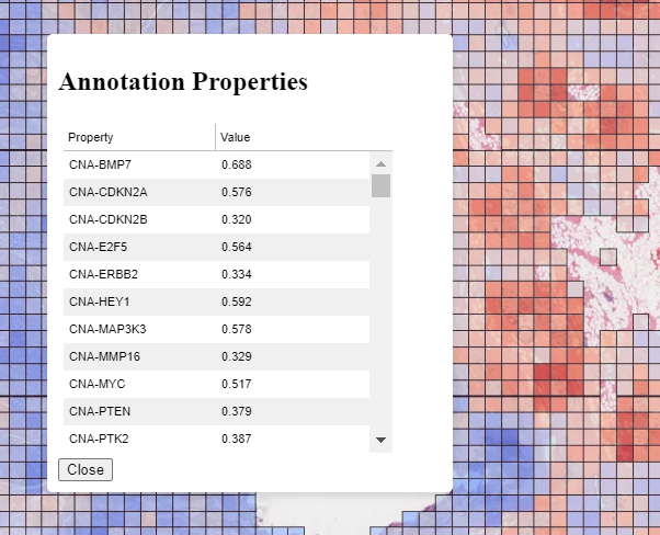
Annotations can be inspected by double-clicking on them. This will open a popup showing the annotation in more detail, and allowing the properties to be viewed in a sortable table. An example can be seen to the right for a patch prediction overlay where multiple targets have been predicted for each patch.
Zoomed Out Plotting
By default, the interface is set up to show only larger annotations while zoomed out. Smaller annotations which would be too small to see clearly while zoomed out will not be displayed. The ‘max-scale’ value can be changed to control the zoom level at which this happens. A larger value will mean smaller annotations remain visible at more zoomed out scale. If you want all annotations to be displayed always regardless of zoom, just type in a large value (1000+) to set it to its max. In the case of very many annotations, this may result in some loading lag when zoomed out.
Multichannel Images
When viewing multi-channel (i.e non-RGB) images such as immunofluorescence, a UI element will be available under the ‘other options’ panel to allow the selection of individual channels in any combination to be displayed. The interface will attempt to get channel color information from the slide metadata, but these can be overriden in this UI too if needed with the color select widget.
Other Options
There are a few options for how annotations are displayed. You can change the colormap used in the colormap field if you are coloring objects according to a continuous property (values should be between 0-1), by choosing one of the matplotlib cmaps. The buttons ‘filled’, ‘mpp’, ‘grid’, respectively toggle between filled and outline only rendering of annotations, using mpp or baseline pixels as the scale for the plot, and showing a grid overlay.
A filter can be applied to annotations using the filter box. For example, entering props[‘score’]>0.5 would show only annotations for which the ‘score’ property is greater than 0.5. See the documentation in AnnotationStore on valid ‘where’ statements for more details.
The main slide view can be made fullscreen by clicking the fullscreen icon in the small toolbar to the immediate right of the main window. This toolbar also provides a button to save the current view as a .png file.
Visualising Image Registration/Transformation
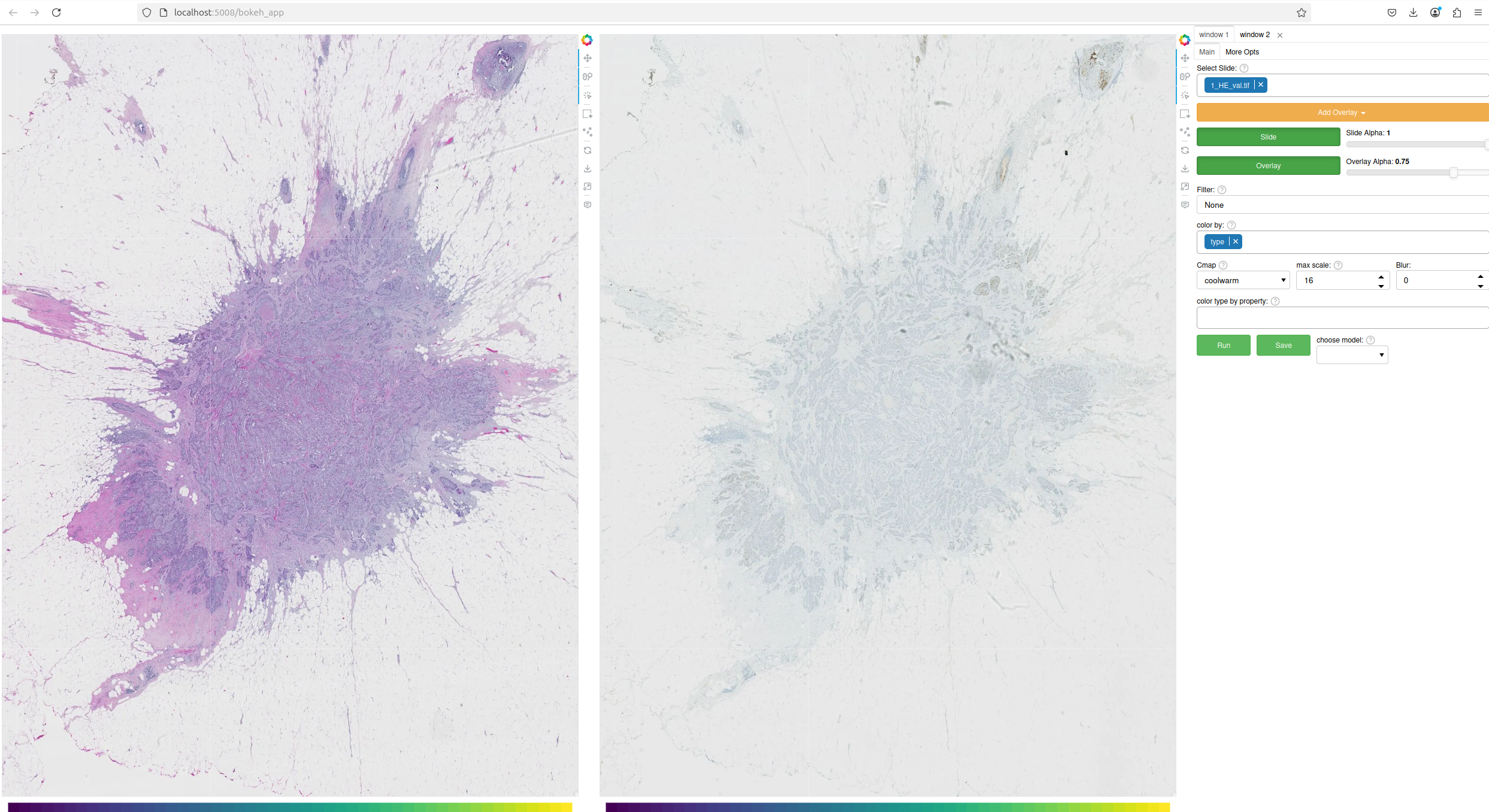
TIAToolbox provides a powerful registration visualization feature that enables intuitive alignment and comparison of histopathology images—such as H&E and IHC-stained slides—without requiring full whole-slide registration. This is particularly useful for quickly inspecting the accuracy of precomputed registration results.
To use this feature, you must supply a precomputed registration matrix (e.g., .mha or .npy file) generated from an affine or deformable registration process. This matrix is used to align the images visually.
Dual Window Mode:
This mode allows side-by-side comparison of registered images.
Steps:
Open Dual Window Mode and load the images.
In one window, open the H&E (source) image.
In the other window, open the IHC (target) image.
Load the registration file (e.g., an .mha or .npy file) as an overlay on the source image.
Overlay Mode:
This mode overlays the registered image directly on top of the source image for visual inspection.
Steps:
Open the H&E (source) image.
Overlay the IHC (target) image on the source image.
Load the registration file (e.g., an .mha or .npy file) as an overlay on the source image.
Note
Always load the target image first when using overlays. If not, the system may incorrectly assume both images are the same, leading to inaccurate transformations. Incorrect ordering may result in misaligned overlays or misleading visualizations.
The order of source and target images must remain consistent with how the registration matrix was computed. This is as most registration algorithms require the dimensions of both the source and target images to perform the registration transformation. The above examples assume that the H&E image is registered to the IHC images, but if instead you have registered the IHC to the H&E image then please change the order of image loading accordingly.
3. Data Format Conventions and File Structure
In the slides folder should be all the slides you want to use, and the overlays folder should contain whatever graphs, segmentations, heatmaps, etc., you are interested in overlaying over the slides.
When a slide is selected in the interface, any valid overlay file that can be found that contains the same name (not including extension) will be available to overlay upon it.
Segmentation
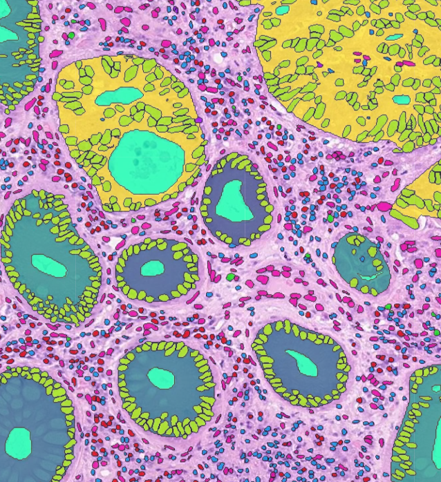
To visualize segmentation, please save your results in the AnnotationStore format (more information about the TIAToolbox annotation store can be found at storage). Other options are GeoJSON (.geojson) or a HoVerNet-style .dat (see hovernet). The GeoJSON and .dat formats can be loaded within the interface but will incur a delay as the data needs to be converted internally into an AnnotationStore for an optimized visualization experience.
If your annotations are in a GeoJSON format following the sort of thing QuPath would output, that should be okay. Contours stored following HoVerNet-style output in a .dat file should also work. An overview of the data structure in these formats is below.
HoVerNet style:
sample_dict = {nuc_id: {
                box: List[],
                centroid: List[],
                contour: List[List[]],
                prob: float,
                type: int
            ... # can add as many additional properties as we want...
                        }
            ... # other instances
            }
Files in this format can be converted to an AnnotationStore using: store_to_dat. This utility function should also be able to handle .dats output from Cerberus.
GeoJSON:
{
"type":"Feature",
"geometry":{
    "type":"Polygon",
    "coordinates":[[[21741, 49174.09],[21737.84, 49175.12],[21734.76, 49175.93],[21729.85, 49179.85],[21726.12, 49184.84],[21725.69, 49187.95],[21725.08, 49191],[21725.7, 49194.04],[21726.15, 49197.15],[21727.65, 49199.92],[21729.47, 49202.53],[21731.82, 49204.74],[21747.53, 49175.23],[21741, 49174.09]]]},
    "properties":{"object_type":"detection","isLocked":false}
}}
Files in this format can be converted to an AnnotationStore using the method:
AnnotationStore.from_geojson().
While data in these formats can be loaded directly into the interface, it is recommended to convert and save them as an AnnotationStore outside the interface, as this will be much faster to load.
TIAToolbox also provides a function to convert the output of PatchPredictor to an AnnotationStore, which can be found at dict_to_store.
If your data is not in one of these formats, it is usually fairly straightforward to build an AnnotationStore out of your model outputs. A small script of 6-10 lines is usually all that is required. There are example code snippets illustrating how to create an AnnotationStore in a variety of common scenarios in the examples section. Most use-cases should be covered in there, or something close enough that a few tweaks to a snippet will do what is needed.
Heatmaps
These should be provided as a low-res heatmap in .jpg or .png format. It should be the same aspect ratio as the WSI it will be overlaid on. When creating the image, keep in mind that black pixels (0,0,0) will be made transparent.
Single channel images can also be used but are not recommended; they should take values between 0 and 255 and will simply be put through a viridis colormap. 0 values will become white background.
Whole Slide Overlays
It is possible to overlay multiple WSIs on top of each other as separate layers simply by selecting them in the overlays dropdown, though if the visualization task can be achieved using another form of overlay, that would be recommended as it will usually be more flexible and faster to load.
Graphs
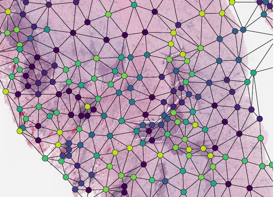
Graphs can also be overlaid. The display of nodes and edges can be toggled on/off independently in the right-hand panel of the interface (note, edges will be turned off by default; they can be made visible by toggling the ‘edges’ toggle in the UI). An example of a graph overlay is shown to the right. Graph overlays should be provided in a dictionary format with keys as described below, saved as a .json file.
E.g.:
graph_dict = {
        'edge_index': 2 x n_edges array of indices of pairs of connected nodes
        'coordinates': n x 2 array of x, y coordinates for each graph node (at baseline resolution)
        }
Additional features can be added to nodes by adding extra keys to the dictionary, e.g.:
graph_dict = {
            'edge_index': 2 x n_edges array of indices of pairs of connected nodes
            'coordinates': n x 2 array of x, y coordinates for each graph node
            'feats': n x n_features array of features for each node
            'feat_names': list n_features names for each feature
        }
It will be possible to color the nodes by these features in the interface, and the top 10 will appear in a tooltip when hovering over a node (you will have to turn on the hovertool in the small toolbar to the right of the main window to enable this, it is disabled by default).
4. Annotation Store Examples
Patch Predictions
Let’s say you have patch-level predictions for a model. The top left corner of each patch, and two predicted scores are in a .csv file. Patch size is 512.
results_path = Path("path/to/results.csv")
db = SQLiteStore()
patch_df = pd.read_csv(results_path)
annotations = []
for i, row in patch_df.iterrows():
    x = row["x"]
    y = row["y"]
    properties = {"score1": row["score1"], "score2": row["score2"]}
    annotations.append(
        Annotation(Polygon.from_bounds(x, y, x + 512, y + 512), properties=properties)
    )
db.append_many(annotations)
db.dump("path/to/filename.db")   # filename should contain its associated slide's name
When loading the above in the interface, you will be able to select any of the properties to color the overlay by.
GeoJSON Outputs
While .geojson files can be loaded in the interface directly, it is often more convenient to convert them to a .db file first, as this will avoid the delay while the geojson is converted to an AnnotationStore. The TIAToolbox AnnotationStore class provides a method to do this.
geojson_path = Path("path/to/annotations.geojson")
db1 = SQLiteStore.from_geojson(geojson_path)
db1.dump("path/to/annotations.db")
Raw Contours and Properties
If you have a collection of raw centroids or detection contours with corresponding properties/scores, you can easily convert these to an AnnotationStore.
centroid_list = [[1, 4], [3, 2]] # etc...
# if it's contours each element is a list of points instead
properties_list = [
    {"score": "some_score", "class": "some_class"},
    {"score": "other_score", "class": "other_class"},
    # etc...
]

annotations = []

for annotation, properties in zip(centroid_list, properties_list):
    props = {"score": properties["score"], "type": properties["class"]}
    annotations.append(
        Annotation(Point(annotation), props)
    )  # use Polygon() instead if it's a contour
db.append_many(annotations)
db.create_index("area", '"area"')  # create index on area for faster querying
db.dump("path/to/annotations.db")
Note that in the above we saved the ‘class’ property as ‘type’ - this is because the UI treats the ‘type’ property as a special property, and will allow you to toggle annotations of a specific type on/off, in addition to other functionality.
Graphs Example
Let’s say you have a graph defined by nodes and edges, and associated node properties. The following example demonstrates how to package this into a .json file:
graph_dict = {'edge_index': 2 x n_edges array of indices of pairs of connected nodes
            'coordinates': n x 2 array of x, y coordinates for each graph node
            'feats': n x n_features array of features for each node
            'feat_names': list n_features names for each feature
            }

with open("path/to/graph.json", "w") as f:
    json.dump(graph_dict, f)
Modifying an Existing Annotation Store
If you have an existing annotation store and want to add/change properties of annotations (or can also do similarly for geometry):
# let's assume you have calculated a score in some way, that you want to add to
# the annotations in a store
scores = [0.9, 0.5]

db = SQLiteStore("path/to/annotations.db")
# use the SQLiteStore.patch_many method to replace the properties dict
# for each annotation.
new_props = {}
for i, (key, annotation) in enumerate(db.items()):
    new_props[key] = annotation.properties  # get existing props
    new_props[key]["score"] = scores[i]  # add the new score

db.patch_many(
    db.keys(), properties_iter=new_props
)  # replace the properties dict for each annotation
Merging Two Annotation Stores
The interface will only open one annotation store at a time. If you have annotations belonging to the same slide in different stores that you want to display at the same time, just put them all in the same store as follows:
db1 = SQLiteStore("path/to/annotations1.db")
db2 = SQLiteStore("path/to/annotations2.db")
anns = list(db1.items())
db2.append_many(anns)  # db2 .db file now contains all annotations from db1 too
Shifting Coordinates
Let’s say you have some annotations that were created on a slide, and you want to grab the annotations in a particular region and display them on a tile from that slide. You will need their coordinates to be relative to the tile. You can do this as follows:
top_left = [2048, 1024]  # top left of tile
tile_size = 1024  # tile size
db1 = SQLiteStore("path/to/annotations.db")
query_geom = Polygon.from_bounds(
    top_left[0], top_left[1], top_left[0] + tile_size, top_left[1] + tile_size
)
db2 = SQLiteStore()
tile_anns = db1.query(query_geom)  # get all annotations in the tile
db2.append_many(tile_anns.values(), tile_anns.keys())  # add them to a new store

def translate_geom(geom):
    return geom.translate(-top_left[0], -top_left[1])

db2.transform(translate_geom)  # translate so coordinates relative to top left of tile
db2.dump("path/to/tile_annotations.db")
5. Config Files
A JSON config file can be placed in the overlays folder to customize various aspects of the UI and annotation display when visualizing overlays in that location. This is especially useful for customizing online demos. An example .json explaining all the fields is shown below.
There are settings to control how slides are loaded:
{
"initial_views": {
    "slideA": [0,19000,35000,44000],    # if a slide with specified name is opened, initial view window will be set to this
    "slideB": [44200,59100,69700,76600]
        },
"auto_load": 1,     # if 1, upon opening a slide will also load all annotations associated with it
"first_slide": "slideA.svs",            # initial slide to open upon launching viewer
Settings to control how annotations are displayed, including default colors for specific types, and default properties to color by:
"color_dict": {
    "typeA": [252, 161, 3, 255],   # annotations whose 'type' property matches these, will display in the specified color
    "typeB": [3, 252, 40, 255]
},
"default_cprop": "some_property",     # default property to color annotations by
"default_type_cprop": {               # a property to color a specific type by
"type": "Gland",
"cprop": "Explanation"
},
There are settings to control the initial values of some UI settings:
"UI_settings": {
    "blur_radius": 0,           # applies a blur to rendered annotations
    "edge_thickness": 0,        # thickness of boundaries drawn around annotation geometries (0=off)
    "mapper": "jet",            # default color mapper to use when coloring by a continuous property
    "max_scale": 32             # controls zoom level at which small annotations are no longer rendered (larger val->smaller
},                              # annotations visible when zoomed out)
"opts": {
    "edges_on": 0,              # graph edges are shown or hidden by default
    "nodes_on": 1,              # graph nodes are shown or hidden by default
    "colorbar_on": 1,           # whether color bar is shown below main window
    "hover_on": 1
},
and the ability to toggle on or off specific UI elements:
"UI_elements_1": {              # controls which UI elements are visible
    "slide_select": 1,          # slide select box
    "layer_drop": 1,            # overlay select drop down
    "slide_row": 1,             # slide alpha toggle and slider
    "overlay_row": 1,           # overlay alpha toggle and slider
    "filter_input": 1,          # filter text input box
    "cprop_input": 1,           # box to select which property to color annotations by ('color by' box)
    "cmap_row": 1,              # row of UI elements with colormap select, blur, max_scale
    "type_cmap_select": 1,      # UI element to select a secondary colormap for a specific type (i.e 'color type by' box)
    "model_row": 0,             # UI elements to choose and run a model
    "type_select_row": 1        # button group for toggling specific types of annotations on/off
},
"UI_elements_2": {              # controls visible UI elements on second tab in UI
    "opt_buttons": 1,           # UI elements providing a few options including if annotations should be filled/outline only
    "pt_size_spinner": 1,       # control for point size and graph node size
    "edge_size_spinner": 1,     # control for edge thickness
    "res_switch": 1,            # allows to switch to lower res tiles for faster loading
}
}
This .json filename should end in ‘config.json’ to be picked up by the interface.
6. OpenLayers frontend
TIAToolbox supports an OpenLayers-based frontend viewer.
There are currently two ways to use the OpenLayers frontend:
show-wsiuses the legacy OpenLayers viewer and loads the slide when the command is started.visualize-betalaunches the experimental dynamic OpenLayers viewer, where slides and overlays can be loaded or changed after the viewer has started.
The experimental viewer is being developed separately so that new viewer
functionality can be tested without changing the existing show-wsi workflow.
Normal users
Normal TIAToolbox users do not need Node.js, npm, Vite or node_modules
to run either viewer.
The generated JavaScript and CSS files are included in the Python package, so
TIAToolbox can be installed and both OpenLayers viewers can be used directly
through the show-wsi and visualize-beta commands.
The npm/Vite setup described below is only required when developing or rebuilding the OpenLayers frontend.
Running the legacy viewer
The legacy OpenLayers viewer is launched using show-wsi.
Run show-wsi with the path to a whole slide image:
tiatoolbox show-wsi --img-input /path/to/slide.svs
Multiple image paths can also be provided to display a slide together with
additional layers. Each path is provided using a separate --img-input
option:
tiatoolbox show-wsi \
  --img-input /path/to/slide.svs \
  --img-input /path/to/overlay.png
Names can also be assigned to the layers using --name. If names are
provided, the number of names must match the number of image paths:
tiatoolbox show-wsi \
  --img-input /path/to/slide.svs \
  --img-input /path/to/tissue-mask.png \
  --img-input /path/to/semantic-segmentation.db \
  --name slide \
  --name tissue-mask \
  --name semantic-segmentation
Annotation layers can also be coloured using --colour-by together with
--colour-map. For example:
tiatoolbox show-wsi \
  --img-input /path/to/slide.svs \
  --img-input /path/to/tissue-mask.png \
  --img-input /path/to/semantic-segmentation.db \
  --img-input /path/to/nucleus-detections.db \
  --name slide \
  --name tissue-mask \
  --name semantic-segmentation \
  --name nucleus-detections \
  --colour-by type \
  --colour-map categorical
The slide and any additional layers are loaded when the server starts.
This viewer uses the legacy OpenLayers frontend files and keeps the existing
show-wsi behaviour.
Running the experimental dynamic viewer
The experimental OpenLayers viewer is launched using visualize-beta.
Slides and overlays can be provided using a base directory containing
slides and overlays subdirectories:
/path/to/data
├── slides/
└── overlays/
Launch the viewer using:
tiatoolbox visualize-beta --base-path /path/to/data
The slide and overlay directories can also be provided separately:
tiatoolbox visualize-beta \
    --slides /path/to/slides \
    --overlays /path/to/overlays
When directories are provided, all the supported files they contain are made available in the Files panel in the top-left corner of the viewer.
Select a slide from the slide dropdown to load it. The available files can be searched by name, and a different slide can be selected at any time without restarting the viewer.
Once a slide is loaded, matching overlays are made available in the overlay dropdown. An overlay is considered a match when its filename contains the filename stem of the selected slide. The available overlays can also be searched by name. Multiple overlays can be loaded and managed using the Layers panel.
Use Clear Overlays to remove all overlays while keeping the current slide loaded. Use Clear Slide to remove the slide and its overlays and return the viewer to its empty state.
Annotation overlays
Annotation overlays loaded through the Files panel can be managed using the Annotations panel.
Annotation types are grouped by their loaded annotation layer. Each type can be shown or hidden, assigned a colour and given a different fill opacity.
Annotations can be coloured by Class, Property or Class + Property. Property colouring uses the selected continuous colour map and shows the property range in the Annotations panel. Only numeric properties available in all loaded annotation layers are shown.
Class + Property shows one selected class and colours it by a numeric property. Other annotation classes are hidden while this mode is active.
In Class and Property modes, Select all and Deselect all can be used to change the visibility of all annotation types at once.
Fill opacity can be adjusted in all three display modes. Enable Link opacity to apply the same opacity to all loaded annotation classes. When it is disabled, only the changed class is affected.
Selecting an annotation highlights its geometry and shows its layer and properties in a movable information card. Closing the card removes the highlight.
Annotation inspection can be enabled or disabled in Settings. Enable Multiple annotation selection to keep multiple annotation cards and highlights open at once.
Default annotation colours can be provided using a JSON file in the root of
the overlay directory. The filename must end in config.json, for example
annotation_config.json:
{
    "color_dict": {
        "Tumour": [214, 39, 40, 255],
        "Stroma": [31, 119, 180, 255],
        "Inflammatory": [44, 160, 44, 255]
    }
}
Types not included in color_dict are assigned colours automatically.
In Class mode, the Export colours button downloads the colours for the
currently loaded annotation types as annotation_config.json. This file can be placed in the
overlay directory and reused when the viewer is started again.
Exported colour files also save colours separately for each annotation layer.
color_dict provides the default colours.
In Class mode, use Import colours to load colours from a JSON annotation
configuration file.
Both color_dict and layer_color_dicts are supported. Layer-specific colours
take priority over color_dict. Colours for classes or layers that are not
currently loaded are ignored.
In Class mode, the Palette control can recolour loaded annotation classes using Automatic or Matplotlib Set1, Set2, Set3, Dark2, Accent, Paired, tab10, tab20, tab20b and tab20c.
Automatic and named palettes assign colours consistently across the currently loaded classes. Similar colours are spaced apart where possible, and if the selected palette does not have enough colours, colours from the other qualitative palettes are used instead of repeating them.
Colours loaded from a configuration file, manually changed or imported are shown as Custom.
In Property and Class + Property modes, the Colour map control supports viridis, plasma, inferno, magma, cividis and turbo.
The viewer can also be launched without predefined directories:
tiatoolbox visualize-beta
In this case, the viewer starts empty without configured slide or overlay directories.
A different port can be specified using --port:
tiatoolbox visualize-beta \
    --base-path /path/to/data \
    --port 5001
The experimental viewer stores the current slide, position and zoom level in the URL. A saved viewer URL can therefore be reopened to restore the slide and view state.
These features are currently part of the experimental visualize-beta
command and do not change the behaviour of show-wsi.
For Developers
Node.js and npm are required when changing or rebuilding the OpenLayers frontend.
Check that they are installed with:
node --version
npm --version
The existing show-wsi viewer is kept separately as the legacy viewer, while
the experimental dynamic viewer uses the main OpenLayers frontend files.
The shared frontend tooling files are:
package.jsondefines the frontend dependencies and build commands.package-lock.jsonrecords the exact dependency versions installed by npm.
Legacy viewer
The legacy viewer files are:
src/main_legacy.jscontains the OpenLayers viewer used byshow-wsi.src/style_legacy.csscontains the legacy viewer styling.vite.legacy.config.jsdefines how the legacy viewer is built.
The generated files for the legacy viewer are:
tiatoolbox/data/visualization/static/openlayers/viewer_legacy.js
tiatoolbox/data/visualization/static/openlayers/viewer_legacy.css
These are served when show-wsi is used.
The legacy viewer template is:
tiatoolbox/data/visualization/templates/index_legacy.html
Experimental viewer
The experimental viewer source is split into the following files and directories:
src/main.jsowns the application-level viewer state and coordinates the map, slide and overlay lifecycle, and the frontend feature controllers.src/api/contains TileServer request helpers for dynamic slide and overlay operations.src/components/contains reusable interface components, such as the searchable file selector.src/controls/contains the map, grid, scale bar and overview map controllers.src/panels/contains the Files, Layers, Annotations and Settings panel controllers.src/utils/contains shared annotation colour, colour and path helpers.src/style.cssimports the experimental viewer styles.src/styles/contains the experimental viewer styling split by feature.vite.config.jsdefines how the experimental viewer is built.
src/main.js remains responsible for coordination between features. The
extracted modules keep individual feature logic separate and receive the state
and callbacks they need from the main viewer rather than owning the overall
application state.
The generated files for the experimental viewer are:
tiatoolbox/data/visualization/static/openlayers/viewer.js
tiatoolbox/data/visualization/static/openlayers/viewer.css
These are served when visualize-beta is used.
The experimental viewer template is:
tiatoolbox/data/visualization/templates/index.html
TileServer
Both viewers share the same TileServer implementation in:
tiatoolbox/visualization/tileserver.py
TileServer uses its legacy option to select the appropriate frontend and
session behaviour.
show-wsi starts the TileServer with:
legacy = True
visualize-beta starts the TileServer with:
legacy = False
The experimental viewer also uses:
tiatoolbox/cli/visualize_beta.pyto provide thevisualize-betacommand.Dynamic TileServer routes in
tiatoolbox/visualization/tileserver.pyfor listing, loading and removing slides and overlays while the viewer is running.
Building the frontend
Run the frontend development commands from:
tiatoolbox/visualization/openlayers/
Install the dependencies with:
npm ci
This installs the exact versions recorded in package-lock.json.
Building the legacy viewer
After changing src/main_legacy.js or src/style_legacy.css, rebuild the
legacy viewer with:
npm run build:legacy
This updates:
viewer_legacy.js
viewer_legacy.css
The legacy build does not remove the generated experimental viewer files.
Building the experimental viewer
After changing src/main.js or any of the experimental modules or styles under
src/, rebuild the experimental viewer with:
npm run build
This updates:
viewer.js
viewer.css
The experimental build does not remove the generated legacy viewer files.
If changes affect both viewers, both builds can be run:
npm run build:legacy
npm run build
The generated JavaScript and CSS files should be committed together with their source changes.
Do not edit the generated JavaScript or CSS files directly because they are generated by Vite.
After rebuilding the frontend, return to the root of the TIAToolbox repository:
cd ../../..
Test the legacy viewer with:
tiatoolbox show-wsi --img-input /path/to/slide.svs
Test the experimental viewer with:
tiatoolbox visualize-beta --base-path /path/to/data
If the OpenLayers or ol-ext version needs to be changed, update it with npm and then rebuild both viewers as required. For example:
cd tiatoolbox/visualization/openlayers/
npm install --save-exact ol@<version>
npm run build:legacy
npm run build
This updates the recorded dependency version and rebuilds the generated frontend files using the new version.